Table of Contents
- What Spout Pouch Filling Line Compatibility Means
- Critical Spout Fitment Dimensions for Machine Compatibility
- How Spout Insertion and Sealing Work on Automatic Lines
- Capping and Torque Specifications
- Filling Nozzle Clearance and Product Flow
- Pouch Handling and Machine Guides
- Changeover Considerations for Multi-format Lines
- Buyer Checklist for Line Compatibility
- Conclusion
Spout pouch filling line compatibility depends on matching fitment geometry to your machine’s insertion, sealing, capping, and filling stations. This guide covers critical dimensions, torque specs, handling requirements, and changeover factors.
What Spout Pouch Filling Line Compatibility Means
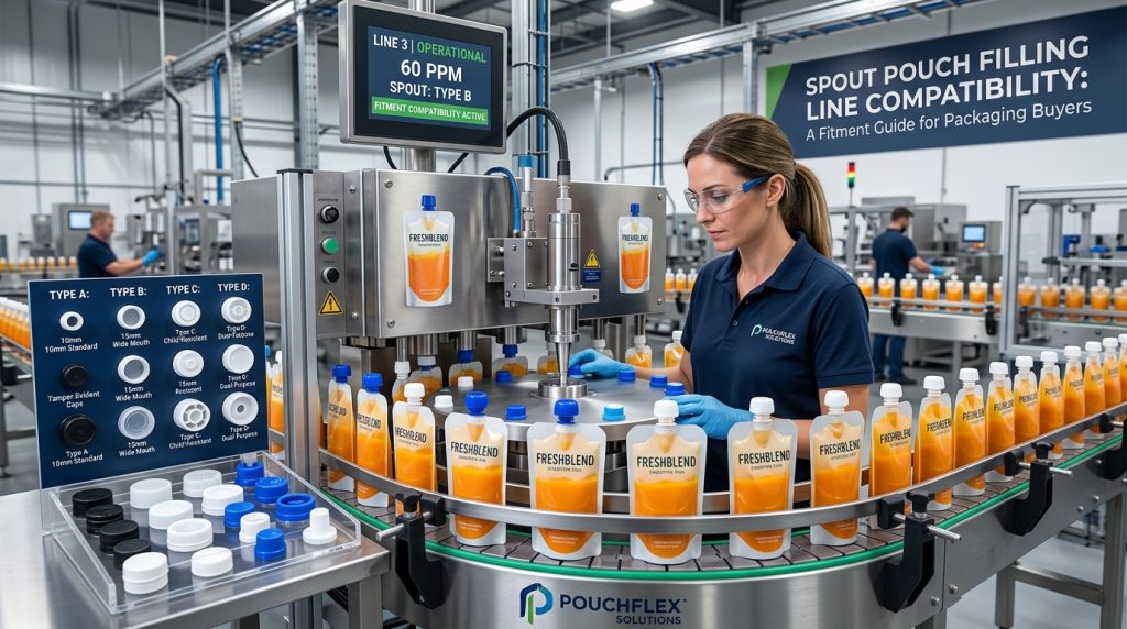
Spout pouch filling line compatibility means your pouch and spout fitment can be automatically fed, opened, filled, sealed, capped, and discharged on a specific filling machine without unexpected downtime or extensive modifications. The two most common obstacles are mismatched fitment geometry (thread size, flange diameter, bore diameter) and insufficient sealing or capping tooling for the spout type.
Before ordering custom spout pouches, packaging buyers should confirm the exact spout specifications against the machine manufacturer’s format requirements. This guide explains the key dimensions, torque parameters, and handling factors that determine whether a spout pouch will run smoothly on your existing or planned filling line. For a deeper look at fitment options, see our guide to spout pouch fitments, caps, pumps, and dispensers.
Critical Spout Fitment Dimensions for Machine Compatibility
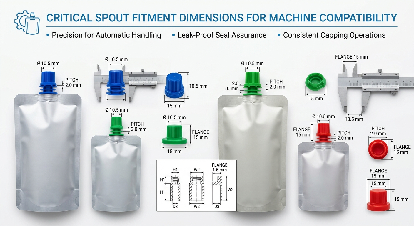
Automatic filling machines use precise rails, chucks, jaws, and starwheels designed for a specific range of fitment sizes. Even a 1 mm difference in flange diameter or thread OD can cause jams, misfeeds, or seal failures. The dimensions below must be verified against your machine’s format specification.
- Thread diameter and neck finish: Common spout thread sizes are 20 mm, 24 mm, 28 mm, 38 mm, and 51 mm. The capping chuck and cap sorter are tooled to one thread profile. Mismatched thread pitch or diameter prevents proper cap application.
- Flange dimensions (outside diameter and thickness): The insertion station grippers hold the spout by the flange. The flange OD must sit within the machine’s allowable range, and the thickness affects how the spout seats in the pouch hole before sealing.
- Overall spout height and cap height: Clearance under the capping head and through transfer starwheels depends on the total height from flange bottom to cap top. A taller spout may require a different capping head or guide rail.
- Bore (orifice) diameter: The opening through the spout must accommodate the fill nozzle and allow product flow. Typical bore diameters range from 8 mm to 12 mm for liquids and up to 20 mm for viscous products.
For a detailed breakdown of spout and cap options, refer to our guide on spout pouch closure types, caps, fitments, and seal design.
How Spout Insertion and Sealing Work on Automatic Lines
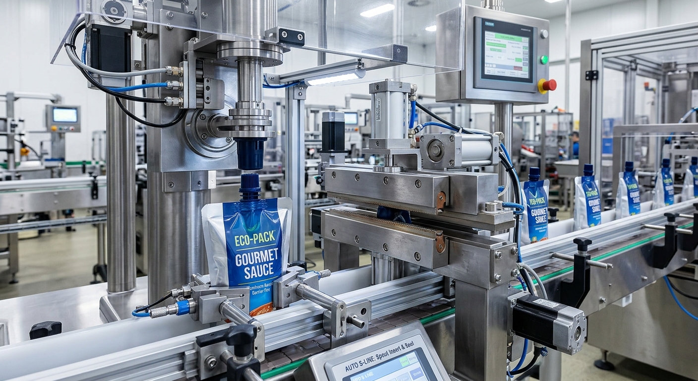
On most rotary or inline spout pouch machines, pre-made pouches with a pre-cut spout hole are loaded into a magazine. A pick-and-place unit orients each spout from a vibratory bowl and inserts it into the hole. The spout flange is then heat sealed to the inner sealant layer of the pouch film. This process requires three things to be perfectly aligned:
- Insertion mechanism compatibility: The spout gripper must match the flange profile without scratching or deforming the part.
- Heat seal jaw profile: The sealing jaw must contact the flange evenly around its full circumference. Irregular flange thickness can cause weak spots.
- Correct sealing parameters: Temperature, pressure, and dwell time depend on the spout material (PP or PE) and the pouch’s inner sealant layer. Typical seal temperatures for PP spouts on PE sealant film are 160–200°C, with 1–3 seconds dwell and 2–4 bar pressure, but these values must be validated for your specific laminate.
Many buyers confuse spout insertion torque with capping torque. Spout insertion on automatic lines is a heat seal process, not a threaded assembly. There is no insertion torque to specify for standard welded spouts. Instead, the key quality metric is seal strength (burst or peel test). Capping torque, on the other hand, applies to the closure and is discussed in the next section. For hot-fill applications, spout and seal must withstand elevated temperatures; see our hot fill spout pouch engineering guide.
Capping and Torque Specifications

The capping station applies the closure to the spout neck. Machine compatibility here depends on the cap design, thread engagement, and required application torque. The following factors must be confirmed:
- Cap type: Standard screw caps, flip-top caps, child-resistant caps, or dispensing pumps each require a different capping head profile.
- Application torque range: Most beverage and food spout pouches use a cap torque of 8–20 inch-pounds (0.9–2.3 N·m), depending on thread size and liner type. Torque must be high enough to prevent loosening during transport but low enough for consumers to open easily.
- Induction sealing compatibility: If the cap includes an induction seal liner, the capping station must be followed by an induction sealer positioned at the correct height for the spout’s foil membrane.
Confirm the capping chuck matches the cap’s outer diameter and drive feature (knurling, ribs, or smooth). Many machine suppliers offer format-specific capping heads that can be swapped during changeover. For more on cap and closure options, read our article on spout pouch closure types.
Filling Nozzle Clearance and Product Flow
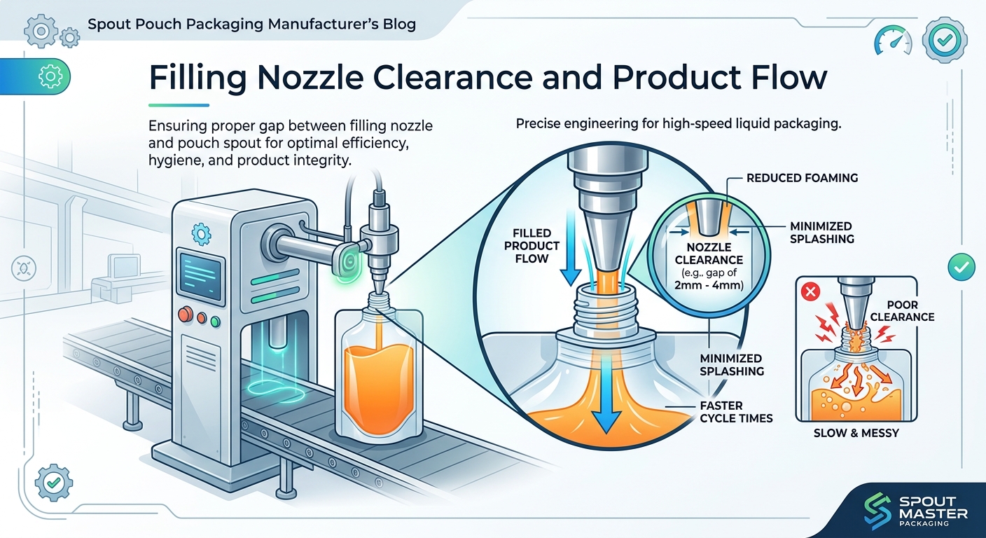
After the spout is sealed, the fill nozzle descends into the spout bore to dispense product. Two compatibility issues arise here:
- Nozzle outer diameter vs. spout bore diameter: The nozzle must fit inside the spout with enough annular clearance for air to escape. A typical rule is at least 2 mm clearance around the nozzle, but this depends on fill speed and product foaming.
- Product viscosity and fill rate: Thick pastes, gels, or products with particulates require a larger bore diameter or a higher fill pressure to achieve required line speed. For example, a 10 mm bore is common for beverages, while a 15–20 mm bore may be needed for sauces or baby food.
If your existing filling machine uses a fixed nozzle, you must specify a spout with a bore opening that accommodates that nozzle. Conversely, a new machine purchase should be matched to the spout size you plan to use across multiple SKUs. The pouch dimensions also affect fill accuracy; see our spout pouch sizes guide for capacity planning.
Pouch Handling and Machine Guides
The pouch body itself must travel through the machine without skewing or falling. Key factors include:
- Spout position: Top center spouts are handled differently from corner spouts. Transfer grippers and guide rails are designed for one orientation. Changing spout location may require different change parts.
- Pouch width and length: The machine’s pitch (distance between stations) and the pouch carrier width must accommodate the pouch flat dimensions. Oversized pouches may hit guide rails or misalign at the sealing station.
- Pouch gusset thickness: Side-gusset pouches have a thicker bottom profile that must fit within the machine’s grip mechanism.
When ordering custom pouches, specify the exact fill line model or provide the machine manufacturer’s format drawing to your packaging supplier. This ensures the pouch and spout combination is designed for your line. For a checklist on evaluating suppliers, see how to evaluate a spout pouch supplier.